A tensile test is a way of determining how something will react when a force is applied to it in tension – when it is stretched. It may be performed to assess the joint strength of two or more components, or to ascertain the strength parameters of a material. For instance, a tensile test on a child’s remote control car could determine the disassembly force of the aerial from the body casing. More fundamentally, the tensile properties of the material from which the toy is fabricated may be determined by tensile testing.
In the 17th century, British physicist Robert Hooke stated “as the extension, so the force”, implying that there is a linear relationship between extension and applied force. This was originally derived for springs but can be applied to most elastic materials. Put another way, when a material is placed under tension, applied force (the stress) is proportional to the amount by which the material deforms (the strain), provided that the elastic limit is not exceeded. This observation is defined by Hooke’s law:
F = -kx
where F is the restorative force, x is the displacement and k is a force (or spring) constant. Put another way,
E = stress/strain
stress is the force applied to the specimen and,
strain is the relative elongation of the specimen from its original length.
E is known as Young’s Modulus, represented as the gradient of the stressstrain curve within the initial linear region. This is an extremely useful value to determine, because it gives a clear indication of how much the material will deform under applied tensile loading. A bungee rope, for instance, must have a low enough Young’s Modulus to guarantee the jumper will achieve a long, thrilling jump without the rope jarring when the slack is taken up, but a high enough Young’s Modulus to ensure the rope is sufficiently stiff to bring the jumper springing back skywards prior to hitting the ground.
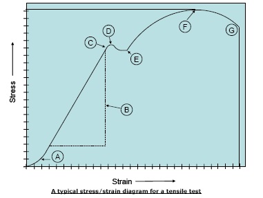
The graph shows a typical plot expected from a tensile test of a ‘Hookean’ material. The labels show the main features, described below. For some materials, the more ductile metals like Aluminium for example; the region denoted by C, D and E is not well defined. The features have been deliberately exaggerated for clarity.
A – This is a feature of system take-up. At very low forces, system can be dominant features and when they are, the output from the load cell is nonlinear. Careful characterisation of the test frame can allow compensation for this. If sample elongation is critical to your measurement for calculating Poisson’s ratio for example, then an independent means of measuring elongation is required.
B – This is the linear portion of the stress/strain curve and shows Hooke’s law in action. The gradient of this line is Young’s modulus, E, a.k.a. Modulus of elasticity, elastic modulus and the Tensile modulus.
C – This is the limit of proportionality, (LOP), where linearity gives way to nonlinear behaviour.
D – This is called the yield point, or yield strength a.k.a. the elastic limit. This point marks the end of the elastic region and the start of the plastic region, within which no extra force is required to further extend the sample. If the test is terminated within this region, the sample will not return to its original dimensions. The end of the plastic region is marked by point E, after which extra force is required to extend the sample further.
F – This is known as the ultimate strength of the material, after which sample break (point G) occurs.
The material may break very soon after reaching the elastic limit (e.g. steel) or it may continue to elongate for a long period of increased loading prior to breaking (e.g. polyethylene sheet). The distance of this elongation can again be a very useful parameter to determine, as can the total elongation at break. It is worth noting that many very brittle materials such as glass and ceramics do not have a clearly distinct yield point, as they will break prior to undergoing permanent deformation. Some materials such as rubber do not obey Hooke’s law.
Tensile testing is commonly used to determine the joint strength of assembled components including, for instance, electronic devices, medical apparatus, packaging, automotive and aeronautical interiors and heavier engineering components.
Example: Determining the tensile load at which a hypodermic needle breaks out of its plastic hub will provide a valuable indication to the designer of its expected performance, or will provide a quantifiable measure of quality to the manufacturer in production.
The following information provides an overview of the fundamental considerations that must be taken into account when performing a tensile test of any nature. Obviously, every test will have its own unique characteristics, and specific test methodology will vary greatly between materials.
To test materials, sample strips of an appropriate width and length, and uniform thickness should be prepared. For materials testing, size and shape of samples are stipulated in relevant standards and samples may be bought ready cut, or a cutting template can be bought. Pre-assembled components should be prepared in such a manner that they will be readily gripped in the correct orientation.
Appropriate grips should be selected that will exert a uniform stress across the whole width of the test piece. In order to achieve this, care must be taken to ensure that the gripping fixtures and the test sample are accurately aligned with the strain axis. Mecmesin offer a comprehensive range of versatile grips and accessories with a variety of clamping actions, including those which close automatically as the tension increases (e.g. a wedge or pneumatic grip), and those which are clamped shut manually prior to commencement of the test (e.g. a vice grip). Selection of appropriate, high quality accessories will minimise the risk of sample slippage or premature failure at the jaw face. For the disassembly force of a joint, Mecmesin offer a range of fixturing designed to accommodate a wide variety of awkwardly shaped samples.
The load should be applied at a uniform travel rate until the required parameter has been determined (e.g.; tensile strength at break; total elongation of material at set force, etc). The crosshead speed should be sufficiently slow to capture a complete tensile profile of the material, but sufficiently fast to complete the desired number of repeat tests within a reasonable timeframe. Mecmesin’s comprehensive range of semi, and fully automated electronic test frames guarantee that the force is applied precisely, which, when accompanied with high capture rate electronics, ensure the tensile profile of the material/component is accurately recorded. Bear in mind that to test the elongation of a particularly stretchy material, you will require a test frame with a sufficiently long travel to effect the required elongation distance, such as the MultiTest 5-x, the MultiTest 5-i, or if required, a larger, twin column Mecmesin test frame. Sufficient repeat test should be performed to assure adherence to relevant standards or internal procedures, and to ensure statistical significance of results and observed trends.
From simple test stand and gauge combinations up to fully automated systems powered by Emperor®, Mecmesin test machines offer varying grades of sophistication for collection, presentation, interrogation and export of results.
Automotive
Electrical & Electronics
Safety, Health, Fitness and Leisure
Medical Applications & Devices
Packages and Packaging Materials
Pharmaceutical Products and Packaging
Plastics, Rubbers and Elastomers
Textile Industry
Paper and Board


