Compliance with current standards now forms a significant part of product development. This has led to stringent quality controls within R&D and production line facilities to:
Force and torque measurement instrumentation are an integral part of the production process, whether in the form of handheld gauges or sophisticated computer-controlled heavy-duty universal testing machines.
This document has been created to help quality control managers, designers and engineers, working on production lines and in research laboratories, get answers to some of the more common technical questions facing them in their application tests.
An awareness of these details will be beneficial to those who wish to begin force measurement tests, and consideration of the following aspects will help you to make an informed decision for your application tests.
Tip 1: Accuracy, Precision and Resolution
Tip 2: Defining your Test Application
Tip 3: Choosing the Correct Loadcell
Tip 4: Selecting the Right Grips/Accessories
Tip 5: Choosing a Suitable Test System
A common analogy, illustrating the difference between accuracy and precision of repeated test data, compares measurements to arrows that are fired at a target, where the ‘bullseye’ represents the expected value.
Accuracy describes the closeness of a measured value to the expected value. The closer it is, the more accurate the measurement is considered to be. Accuracy is commonly quoted in terms of the full scale reading of the instrument (%FS, %FSD, %FSR, %FSO) and sometimes in terms of the % of indicated reading. These are important distinctions to make, as an accuracy of ±0.1%FS means that, for a 1000 N loadcell, at 10N, the accuracy is ±1N but if accuracy is quoted as 0.1% of indicated reading then at 10N the error is only 0.01N.
Where several measurements are made, precision or repeatability, is determined by how close they are to each other. It is possible to have very high precision but low accuracy. Calibration should retain precision and improve accuracy.
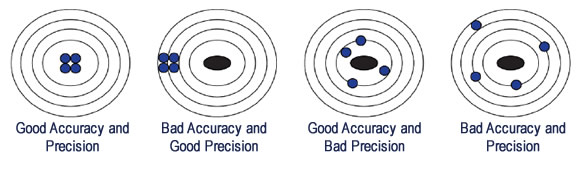
Resolution is different from accuracy and precision. It is defined as the smallest change that can be displayed or recorded by an instrument. To continue with the arrow/target analogy, resolution is the diameter of the arrow. The better the resolution is, the finer the detail will be. In most cases the resolution of an instrument is better than the stated accuracy. For example: A measurement of ±0.01N can be shown on the display, but the accuracy of the instrument may only be ± 0.05N.
Broadly speaking, product or material tests fall into one of three categories:
When testing products, rather than raw materials, more descriptive terms like pulling, pushing, crushing, bending, turning, twisting, tearing, etc are used, all of which fit into these three types of test.
Specimen properties and test type are the main parameters for choosing the right force or torque product with which to perform tests.
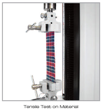
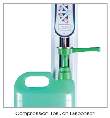
For example, if your specimen stretches easily and requires a tensile test, then a single-column machine with an extended travel will possibly be more appropriate than a twin-column test system. If you have a large, solid specimen for top-load or compression testing, then the opposite will be required.
Are there any European, ISO, ASTM or other standards that apply to your test? If there are, they may help determine your system requirements.
Avoid over-specification. While future-proofing can be wise, there is little advantage in specifying an over complicated test system that an operator, performing routine tasks on a daily basis, will find complicated or difficult to use.
Extensometry
Does your test really need the ultra-high displacement accuracy provided by an extensometer? Certain ASTM, ISO standards call for "extensometers" which measure the deformation directly on the sample instead of measuring crosshead travel. But extensometers can be an expensive addition!
Interpreting the Manufacturers Specification
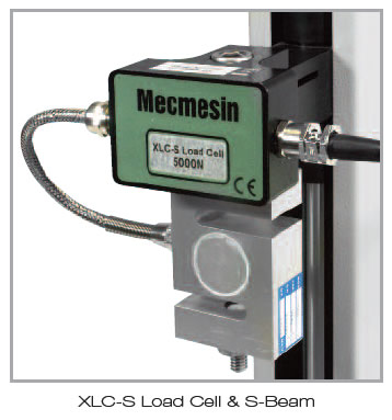
The heart of the force measurement system is the loadcell. When specifying a loadcell, the parameters of interest to most people include capacity and non-linearity.
Some manufacturers quote non-linearity in terms of %FSD or %FSO, and some in terms of % of reading or readout (%RO).
Each manufacturer will tell you that the figure they quote is better than the other. The truth, as is often the case, is somewhere in the middle!
Example
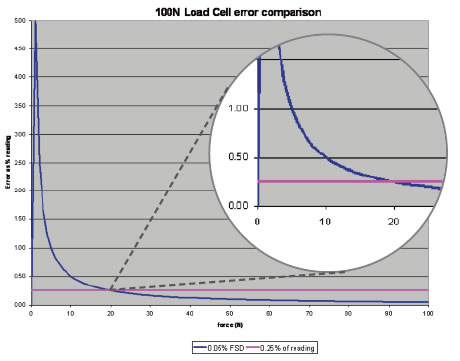
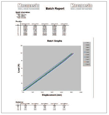
Take an application that requires a 100 N loadcell. One manufacturer quotes the error as 0.05% FSD; another quotes 0.25%RO, both between 1% and 100% capacity. The graph below shows the error, as a percentage of reading for both loadcells, across the range of the loadcell.
From the graph, it is clear that if the loadcell sees mostly loads of <20% of="" its="" capacity="" then="" the="" device="" quoted="" as="" 0="" 25="" ro="" is="" a="" better="" product="" however="" this="" would="" be="" poor="" choice="" for="" particular="" application="" loadcell="" 05="" fsd="" quickly="" outperforms="" rival="" at="" beyond="" 20="" p="">
It is good practice to select loadcells to operate between 10% and 90% of capacity for the majority of its use. For this example, the loadcell quoted as having a non-linearity of ±0.05% FSD is a better choice. If lower capacities are generally expected, then a loadcell of lesser capacity is recommended to ensure measurement errors of 5%RO at 1% of capacity are avoided.
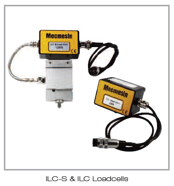
Self identification and/or calibration. “Plug-and-Play”
Does the loadcell have a method of identifying itself to the machine? If it does not, then you may find that every time you change a load cell you have to input the serial number and capacity so the machine knows what is there. This can be very laborious and tedious. As well as self-ID, some so-called ‘plug-and-play’ load cells also have their calibration data stored with them so that as well as telling the test machine what it is, it also tells it the calibration curve.
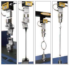
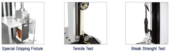
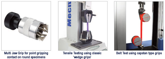
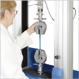
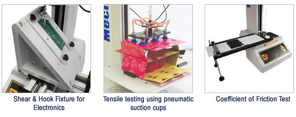
Choice of grips and accessories will depend entirely upon the type of test, as well as the size, shape and material of the specimen to be tested, but when faced with a large selection of standard grips, it may not always be clear which is the best option for you. In many cases a general, all-purpose grip like a wedge grip will be the right choice, but in many others they may not allow the best possible result accuracy. For this reason, when thinking about grips, it is important to define the following:
1. The type of test; tension or compression?
2. The specimen’s size and material structure; the grip should be neither too small or too big.
3. The environment conditions.
Even though wedge grips are versatile, it may be incorrect to select these fixtures for the measurement of a fragile specimen. The structure of the wedge grip is heavy and they have serrated jaws, which may easily distort and damage or worse, break the material. Therefore, it is recommended that wedge grips are used wherever possible for testing specimens constructed of harder materials and that require a higher load capacity. Fragile textiles may be better tested using, say, a spring loaded roller grip, for example. As always, if unsure, talk to your local sales-engineer who should be able to match the correct grip to your application.
The size of grip face is an important consideration, especially when testing solid, stiff materials. If the grip face is too wide or narrow, or if the grip is too tight, then there may be an uneven contact on the specimen resulting in damage or even breakage at an unnatural point in the specimen. This in turn may lead to misleading results.
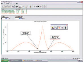
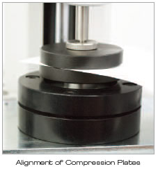
Alignment
Maintaining alignment of the applied force in a tensile or compression test is important in obtaining an accurate result. Off-axis loading can introduce unwanted stresses on the specimen and system producing errors in the loadcell reading, which can cause premature breaks within the specimen and incorrect results.
Self-aligning grips are available for some applications, but more unusual applications will require a custom-made grip solution.
Customised grips for specific applications
For situations where off-the-shelf solutions do not exist, it is important that your supplier has a track record of providing custom solutions and that you can work with them to develop the most effective solution.
Test Systems come in four basic forms:
The following is a summary of the different force test systems available:
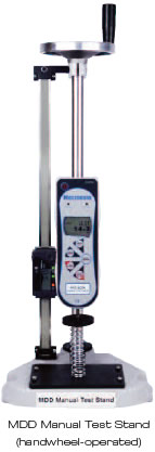
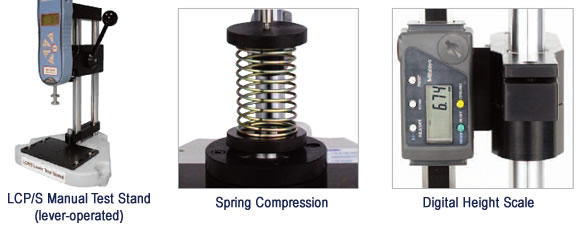
Manual stand
These are normally lever or handwheel operated and used in Manual test stands with a force gauge or other force sensor.
However, different operators will move the crosshead of manual stands at different speeds, so tests are much less repeatable compared to motorised systems.
Some manual test stands may have the possibility to fit an optional height scale to measure displacement. Check with your supplier to see if your stand has this option.
Motorised stand
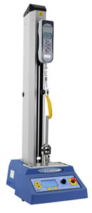
A basic motorised test stand can be optimised with a digital force gauge to provide repeatable and consistent force measurement for simple tension and compression tests.
This configuration of test system is mainly used in production areas where testing throughout speed and accuracy are the main priorities.
Console-controlled system
These semi-automatic systems are programmable to a high degree and incorporate more functionality than force gauges, yet are not as sophisticated as software-driven test machines.
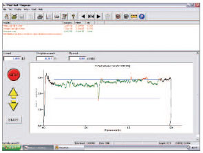
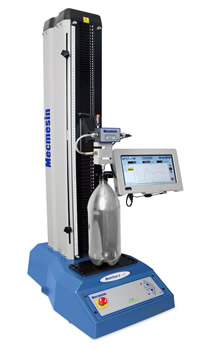
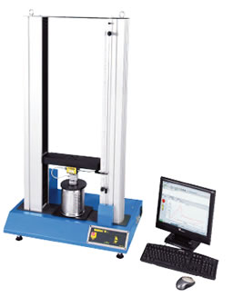
Computer-controlled systems
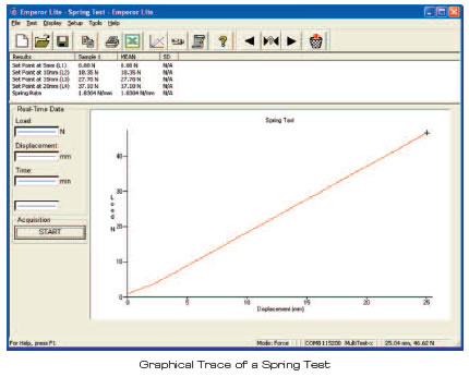
To perform more sophisticated test measurements, particularly where a graphical trace of load/displacement is required, computer-controlled systems are the best solution. They offer the highest degree of repeatability and accuracy, as well as in-depth analysis capabilities.
Test Software
A poorly designed software package, accompanying the test system however, can leave the user more confused!
Things to consider when looking at or being shown force test software are:
Does it have…